Setup
Preface
Disclaimer
Always ensure you have the correct tools and training before beginning installation.
Attempting installation without the specified tools may result in improper assembly, equipment damage, or injury.
Before beginning installation, confirm that all required tools and components are available.
Site preparation must be completed before installing the derail system.
Personal Protective Equipment (PPE)
PPE Advisory
All required personal protective equipment must be equipped before transport, maintenance, or assembly.
-
Hard Hat
-
Earplugs or Earmuffs
-
Safety Glasses
-
Gloves
-
Steel Toe Footwear
-
High Visibility Clothing
Tools and Equipment
-
Measuring Tape
-
Tamping Pick or Pickaxe
-
Multimeter
-
Metric Allen Key Set
-
Adjustable Wrench x2
-
1/8" Slotted Screwdriver
-
Level (Bubble or Digital)
-
Digital Hanging Scale/Fish Scale (Reccomend 60+ Lbs. rating)
-
Cordless Drill with Drill Bit Set
Towing
Towing Advisory
The trailer is not registered for towing on public roads. The Portable Crossing Guard must be transported via flatbed when traversing public roads.
- Follow the procedure described in the Maintenance section titled "Before Storage or Transport".
Site Preparation
Check Clearance
Before finalizing trailer placement or beginning system operation, verify that all mounted components — particularly the arm assembly and sign structure — have adequate clearance in their intended orientation and operating range.
Step 1: Verify Arm Orientation
-
Confirm that the arm assembly is installed facing the correct direction relative to the trailer frame.
-
The pivot or hinge side should align with the mounting reference point specified in the assembly drawing.
-
Ensure there are no obstructions above or beside the arm that could interfere with its full range of motion.
Step 2: Check Sign Orientation
-
The sign face should be perpendicular to the direction of approaching traffic or as required by the installation plan.
-
Verify that the top and bottom edges are parallel to the trailer deck once the trailer is fully leveled.
-
If applicable, confirm that the sign conforms to MUTCD visibility and height requirements. The lower edge of the sign should typically be at least 7 ft (2.1 m) above the ground surface in pedestrian areas, or as required by local code.
Step 3: Measure Operational Clearance
Electrical Lines
Do not attempt setup in area where the arm may be in conflict with electrical/power lines.
-
Determine the required arm length needed for the installation site.
-
Maintain a minimum of 12 in (305 mm) of clearance from any moving or rotating component to nearby surfaces, fixtures, or cables.
-
If operating near buildings or trees, confirm that the arm and sign have unrestricted motion through their full intended range.
Check Levelness
Step 1: Inspect the Ground Surface
-
Choose a compact, load-bearing surface such as concrete, asphalt, or well-compacted gravel.
-
Avoid locations with loose soil, soft clay, grass, or sand, as these may settle unevenly under the trailer’s weight.
-
Ensure there are no depressions, mounds, or large stones beneath the jack points. These can cause twisting of the frame or difficulty in leveling.
Step 2: Assess Surface Drainage
-
Select an area with good runoff so water will not pool under or around the trailer.
-
Avoid low-lying areas that retain moisture, which can cause the trailer to settle into the ground.
Step 3: Check for Slope and Elevation
Levelness
Operating the trailer on an uneven or unstable surface can result in frame misalignment, inaccurate leveling, or equipment damage.
-
Use a bubble level or laser level to check the surface in both directions.
-
The surface should not vary by more than ½ inch over the length of the trailer (12 ft) or ¼ inch across the width (8 ft).
-
If the variation exceeds these limits, adjust by relocating the trailer or using leveling pads under the jacks.
Step 4: Prepare the Contact Area
-
Clear debris, gravel clusters, or vegetation from under each jack location.
-
If the surface is uneven, place solid wooden or composite blocks beneath the jacks to distribute load evenly.
-
Never use rocks, bricks, or cinder blocks, as they may fracture under pressure.
Determine Solar Angle
-
For optimal charging performance, the solar panel must receive unobstructed, direct sunlight between 10:00 AM and 3:00 PM.
-
Ensure there is no shading from nearby structures, railcars, vegetation, or other equipment during these hours.
-
Controller enclosure may be moved along battery enclosure rails to allow clearance for the solar panel.
-
If the site receives limited sunlight or experiences partial shading, a second solar panel may be installed to maintain adequate system charging capacity.
Step 1: Determine Panel Direction
-
For installations north of the Equator, the solar panel should face south for optimal efficiency.
-
Observe the site and ensure that the solar panel will receive sun once installed.
-
Two locations with 1/4"-20 threaded stud patterns are provided for mounting the solar panel and light assemblies.
-
The solar panel must be mounted on the stud pattern closest to the side of the device that will receive the most sunlight.
Step 1: Measure Tilt Angle
The optimal tilt angle for solar panel efficiency depends on the latitude of the installation site.
-
Use a maps or GPS app to measure the site latitude.
-
Set the tilt angle equal to the latitude.
Example
Latitude = 38.2° → Tilt angle = 38.2°
Step 2: Seasonal adjustments:
-
Winter = Latitude + 15°
-
Summer = Latitude – 15°
-
Spring/Fall = Latitude only
Example
Spring/Fall tilt angle = 38.2°
Winter tilt angle = 38.2° + 15° = 53.2°
Summer tilt angle = 38.2° – 15° = 23.2°
Leveling the Trailer
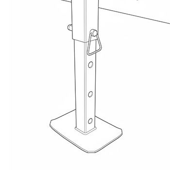
The trailer is equipped with four corner-mounted leveling jacks, one at each corner of the frame. These jacks are used to stabilize and level the trailer after it has been positioned at the installation site.
Level with Corner Jacks Only
Do not use the fifth-wheel jack (tongue jack) to support or level the trailer. The fifth-wheel jack is intended only for hitching and towing. Using it for leveling may cause frame distortion or unsafe loading.
Step 1: Preparing to Level
-
Inspect the ground. Verify that the surface beneath each jack is firm, flat, and load-bearing. If the site is gravel or soil, place a concrete paver, composite pad, or steel plate beneath each jack foot to prevent sinking or shifting.
-
Check jack condition. Ensure each jack is free of rust, bends, or mechanical damage. Confirm that all mounting bolts are tight and that the jack threads or screw mechanisms move smoothly.
-
Confirm travel range. Each jack must have sufficient travel to raise the trailer until the wheels are just off the ground. This ensures all load weight is transferred to the jacks for accurate leveling.
Step 2: Leveling Procedure
-
Park the trailer in the desired position and set the wheel chocks to prevent rolling.
-
Disconnect the trailer from the towing vehicle if necessary.
-
Lower the corner jacks, starting with the rear jacks to stabilize the frame.
-
Lower each jack until it makes firm contact with the ground or paver.
-
Then lower the front jacks, adjusting each incrementally.
Step 3: Adjust to Level
-
Place a bubble or digital level on the trailer frame or deck.
-
Adjust opposing jacks (A–C and B–D, see Figure 4-1) in small increments until the trailer is level front-to-back and side-to-side.
-
Continue fine adjustments until the trailer frame is fully level and stable, and all four jacks share the load evenly.
Step 4: Verify Clearance and Levelness
-
Ensure the wheels are off the ground and the jack arms are extended within safe limits.
-
Check that arm, lights, and crossbuck meet MUTCD height requirements relative to roadway.
-
The trailer must remain stationary and rigid when moderate force is applied to any corner.
Determining Arm Length
Multiple arm sections are provided for installations requiring specific arm lengths. Before proceeding with arm installation, determine the
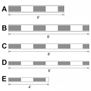
| Designation | Description | Length |
|---|---|---|
| A | Aluminum Arm Section | 8 ft. |
| B | Aluminum Arm Section | 6 ft. |
| C | Fiberglass Arm Section | 8 ft. |
| D | Fiberglass Arm End Section | 8 ft. |
| E | Fiberglass End Section | 4 ft. |
For installations from 5'-8': use sections B + E.
For installations from 8'-22': use sections A + C + D.
Setup
Levelness
Trailer leveling must be complete before proceeding with setup.
Weather
Before beginning trailer setup, check weather forecast. Do not attempt setup in high winds or lighting.
Crossing Arm Setup
Tip
Refer to the Western Cullen Hayes service and Installation manual for detailed arm installation and counterweighting instructions.
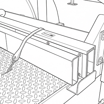
Step 1: Unload the Arm Sections
-
Ensure proceeding steps have been completed to determine the correct arm length.
-
Locate the crossing arm sections in the holders on the left and right sides of the trailer.
-
Remove the rubber tie straps securing the arm sections and lift sections upward to remove.
Step 2: Assemble the Crossing Arm
-
Install the arm sections in sequential order. Use only the sections needed for the installation length.
-
Allow telescoping sections to overlap by at least 12".
Step 3: Secure the Crossing Arm
-
Verify that telescoping arm sections overlap by at least 12".
-
Using a 3/8" drill bit, drill bolt holes through each of the overlapping sections, 8" away from the end of each section per the diagram.
-
Remove any metal or fiberglass shavings from the drilled holes.
-
Insert provided 3/8" bolts, washers, and nuts to secure the arm.
-
Snug arm bolts with a wrench, do not overtighten.
Counterweight Setup
Counterweight Warning
Do not apply counterweight before the roadway gate arm is installed
Counterweight Blocker Plate
Do not remove the pre-installed counterweight blocker plate when installing the counterweights. Doing so may result in damage to equipment from improperly placed counterweights.
Step 1: Apply Initial Counterweight
-
Remove the counterweight retaining nuts.
-
Place one counterweight on each side of the crossing arm.
Step 2: Weigh the Arm
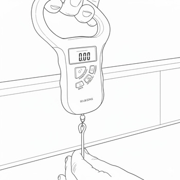
-
Using a digital hanging scale/fish scale, weigh the arm in its final installed configuration.
-
Place the scale 10 feet from the center of the arm pivot point.
-
Refer to the counterweight tables located on Page 22 of the W.C. Hayes 3597 Series OEM manual - "TABLE OF WEIGHT AND VERTICAL TORQUE VALUES FOR FIBERGLASS AND ALUMINUM/FIBERGLASS GATE ARMS: OBLONG COUNTERWEIGHTS WITH ALUMINUM COUNTERWEIGHT ARMS"
-
Add or remove counterweight plates, checking with scale until proper weight is reached for arm length.
Step 3: Secure Counterweight
-
Add counterweight retaining nuts and washers to secure plates. Tighten til snug, do not overtighten.
-
Stow unused counterweights in counterweight holder.
Solar Panel Setup
Step 1: Set Solar Panel Rotation
-
Remove the banding straps holding the solar panel in place.
-
Loosen the solar panel pipe receiver bolts and rotate the panel to the desired direction.
-
Tighten the pipe reciever bolts to lock the solar panel rotation.
Step 2: Set Solar Panel Inclination
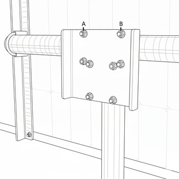
-
Loosen the U-bolt nuts labeled A and B until the panel tilts freely.
-
Rotate the panel to the desired inclination.
-
Tighten U-bolt nuts A and B to lock the solar panel inclination.
-
Snug U-bolts with a wrench so that the solar panel will not fall out of postion. Do not overtighten nuts.
Roadway Lights Setup
Roadway Lights Orientation
The direction of the roadway lights are set by the manufacturer, please return to TXRX for reconfiguration or contact a TXRX representative for on-site instructions.
Bell Setup
Bell Orientation
The direction of the bell is set by the manufacturer, please return to TXRX for reconfiguration or contact a TXRX representative for on-site instructions.
- Refer to Western Cullen Hayes manual for detailed bell instructions.
Crossbuck and Antenna Setup
-
Locate the turnbuckle attached via cable to the crossbuck assembly.
-
Pull down on the turnbuckle, raising the crossbuck assembly to a 90° angle.
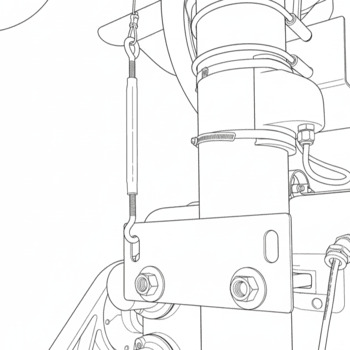
-
Hook the turnbuckle to the retaining plate as shown in the above figure.
-
Tighten the turnbuckle until all slack is removed from the cable, securing the crossbuck assembly.
Electrical
Addressing the Crossing
Within the controller enclosure, an array of DIP switches are visible. These switches set the address of the crossing.
-
The DIP switches use binary addressing to allow one remote to be used with multiple crossing systems.
-
Each crossing in an installation must use a unique address.
Connecting the Solar Panel
-
Connect battery solar jack to solar plug attached to panel.
-
If using two panels, use the provided Y-splitter to connect both panels to the battery input.
-
Ensure all connections are secure and fully seated.
Connecting the Gate Arm Lights
-
The crossing lights are located in the remote storage box on the trailer deck.
-
Refer to the page 15 of the W.C. Hayes 3597 Series OEM manual for detailed installation instructions.
-
Use the provided self-tapping screws to mount the lights to the arm.
-
Use the provided cable clips to affix the cable. Leave slack in the cable for drip points.
-
For installation distances, refer to page 15, figure 8 of the W.C. Hayes 3597 Series OEM manual - "Suggested Roadway Gate Arm Light Spacing"
-
Connect light cable to controller.
-
Ensure all connections are secure and fully seated, and that lights are receiving power.