Maintenance
Maintenance Schedule
To ensure safe operation and performance of the device, regular maintenance should be completed according to the following table. Detailed maintenance procedures are outline further in this section.
| Interval | System | Task | Tools / Materials | Notes |
|---|---|---|---|---|
| Before Each Tow | Tires | Check tire pressure and condition | Tire pressure gauge; air compressor | Inflate to rated PSI; inspect for cracks or wear |
| Before Each Tow | Tongue Jack | Inspect and lubricate | Lithium grease; rags | Check for smooth movement |
| Every 60–90 Days (Storage) | Battery Bank (24 V AGM) | Recharge and inspect terminals | Smart 24 V charger; voltmeter; brush; gloves | Maintain 25.6–26.4 V; avoid overcharging |
| Every 6 Months | Solar System | Check output and sunlight exposure | Multimeter; cloth | Clean panels; confirm clear sunlight 10 AM–3 PM |
| Every 6 Months | Leveling Jacks | Clean and lubricate screw shafts and pivots | Lithium grease; rags; brush; gloves | Prevents corrosion and binding |
| Every 12 Months (In Use) | Battery Bank (24 V AGM) | Recharge and inspect terminals | Smart 24 V charger; voltmeter; brush; gloves | Maintain 25.6–26.4 V; avoid overcharging |
| Every 12-24 Months | Fasteners & Hardware | Inspect and retighten | Socket set; torque wrench | Replace any rusted hardware |
Jack Maintenance
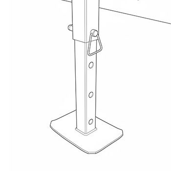
To ensure smooth operation and prevent corrosion, the trailer’s corner leveling jacks should be lubricated every six (6) months or after exposure to rain, road salt, or dusty environments. Regular lubrication extends jack service life and reduces wear on mechanical threads and pivot points.
Required Materials
-
Light machine oil or multi-purpose lithium grease
-
Clean rags or disposable shop towels
-
Small brush or aerosol applicator with extension nozzle
-
Protective gloves and eyewear
Lubrication Procedure
Step 1: Inspect the Jacks
-
Ensure the trailer is parked on a level surface and the jacks are fully retracted.
-
Visually inspect each jack for dirt, rust, or accumulated debris.
-
Wipe the exposed screw shafts, pivots, and housings clean with a rag.
Step 2: Extend the Jacks
-
Use the crank handle or power drive to extend each jack halfway.
-
This exposes the main screw threads and inner guides for cleaning and lubrication.
Step 3: Clean the Mechanisms
-
Remove any old grease, dust, or grit using a clean rag.
-
For stubborn buildup, use a mild solvent (such as mineral spirits) and allow all parts to dry completely.
Step 4: Apply Lubricant
-
Using a brush or nozzle, apply a thin, even coat of lithium grease to the screw threads, pivot pins, and moving joints.
-
For enclosed gear housings, apply a few drops of light oil through the lubrication port (if equipped).
-
Operate the jack through its full travel range twice to distribute lubricant evenly.
Step 5: Wipe and Retract
-
Wipe away excess grease or oil to prevent dirt accumulation.
-
Fully retract the jacks and confirm smooth operation without binding or noise.
Step 6: Repeat for all Corners
-
Perform the same cleaning and lubrication process for each of the four jacks.
-
Check for uniform movement and equal resistance among all jacks.
Battery Maintenance
Absorbent Glass Mat (AGM) batteries require periodic recharging to maintain capacity and ensure reliable system performance. Even when the trailer is not in active use, the batteries should be recharged on a regular schedule to prevent sulfation and capacity loss.
Active Systems (with Solar Input)
-
When solar panels are connected and operational, the charge controller will maintain the 24 V battery bank automatically.
-
Verify that system voltage remains above 25.2 V during regular use.
-
If voltage drops below 24.4 V, perform a full recharge using an approved external charger.
Inactive or Stored Systems
-
If the trailer is stored indoors or disconnected from solar power:
-
Recharge every 60–90 days using a compatible 24 V AGM charger or a dual 12 V charger configured for series connection.
-
Maintain resting voltage between 25.6–26.4 V for long-term storage.
Charging Procedure
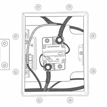
Step 1: Inspect the Battery Bank
-
Check all terminals, interconnect cables, and fuses for corrosion or looseness.
-
Clean terminals using a non-metallic brush and verify tight mechanical connections.
Step 2: Select an Appropriate Charger
-
Use a smart charger rated for 24 V AGM batteries with automatic bulk, absorption, and float modes.
-
Charging profile should reach 28.8–29.4 V during the absorption phase and hold 26.4–27.0 V during float mode.
-
Avoid unregulated or “boost” chargers, which can cause overcharging and thermal damage.
Step 3: Connect the Charger
-
Attach the positive (red) lead to the battery bank’s positive (+) terminal and the negative (black) lead to the negative (–) terminal.
-
Confirm correct polarity and tight contact before turning on the charger.
Step 4: Monitor Charging Progress
-
Allow charging to continue until the battery reaches 100 % state of charge, as indicated by charger status or stabilized current.
-
When charging completes, verify voltage has settled to approximately 26.0–26.4 V after one hour at rest.
Step 5: Disconnect and Record
- Turn off the charger, disconnect leads in reverse order, and note the recharge date, final voltage, and any observations in the maintenance log.
Before Storage or Transport
Disconnect Solar from Battery
Warning
Keep clear of crossing arm travel path when disconnecting the battery. The crossing arm will come down immediately when powered off.
The solar panel must be disconnected when not actively in use charging the battery.
Step 1: Open Disconnect Cover
- Locate and open the quick disconnect hatch on the top of the battery box.
Step 2: Disconnect Solar Panel
-
Verify all personnel, equipment, and crossing components are clear of the arm travel path.
-
Flip the lever to disconnect the solar panel from the battery.
-
If raised, the crossing arm will fall to its down position.
Step 3: Close Cover
- Close and latch disconnect cover.
Secure the Crossing Arm
Step 1: Remove the Lights
-
Disconnect the lights from the controller.
-
Unscrew the self-tapping screws fastening the lights to the arm.
-
Stow the lights in the accessory box.
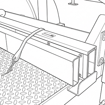
Step 1: Disassemble the Crossing Arm
-
Verify that the arm is in the down position.
-
Remove the crossing arm sections in reverse installation order.
Step 2: Stow the Crossing Arm
-
Locate the crossing arm holder on the deck of the trailer.
-
Insert the arm sections into the holder and secure with provided rubber tie straps.
-
Stow the shortest fiberglass extension section inside the short metal section, to prevent it coming loose during transport.
Step 3: Remove and Stow the Counterweights
- Remove the nuts securing the counterweights.
!!! warning "Counterweight Blocker Plate Do not remove the counterweight blocker plate when removing the counterweights. Doing so may result in damage to equipment from improperly placed counterweights.
-
Remove the counterweight plates in reverse installation order.
-
Locate the counterweight holder on the deck of the trailer.
-
Stow the counterweights and secure with the counterweight nuts.
Step 4: Secure the Arm
-
Use banding straps around the actuator mechanism to prevent the arm from moving.
-
Wrap actuator and arm with shrink-wrap for protection during transport and storage.
Secure the Solar Panel
-
Rotate solar panel to shipping position.
-
Secure the solar panel using banding straps.
Towing Instructions
Towing Advisory
The trailer is not registered for towing on public roads. The Portable Crossing Guard must be transported via flatbed when traversing public roads.
-
Check leveling and tongue jack lubrication.
-
Check tire air pressure.
-
Fully retract leveling jacks using the crank, and attach the pin to secure jacks in highest location.
-
Ensure that leveling jacks are pinned at the highest hole location before moving the trailer to avoid damage to equipment.
-
Only use tongue jack during towing.